31+ phase locked loop block diagram
A Phase Locked Loop Working is basically a closed loop system designed to lock the output frequency and phase to the frequency and phase of an input signal. Analog phase locked loops are generally built with an analog phase detector low pass filter and VCO placed in a negative feedback configuration.

Ne567 Datasheet Tone Decoder Phase Locked Loop And Example Circuits Simple Electronics Function Generator Circuit
IC 565 is the most commonly used phase locked loop IC.
. A new phase sequence detector for the three-phase rotary loads Automated load balancers can swap. The pin diagram of IC 565 is shown in the following figure. A digital phase locked loop uses a digital.
Figure 931 illustrates a basic block diagram of a PLL that uses an input clock signal and a voltage-controlled oscillator VCO in a closed-loop configuration to generate an output clock. In this video we shall discuss the following points. Above is the image of a general phase lock loop block diagram.
Block diagram of an LTE transceiver employing a polar transmitter we have 9 Pictures about Block diagram of an LTE transceiver employing a polar transmitter like PPT - PLL Phase. Loop phase diagram block locked lock figure analog vco. This block diagram is similar to the block diagram of the CD4046B IC chip since that chip is a PLL chip.
The block diagram of a PLL including a frequency divider is shown in Figure 1117A signal of frequency f d is generated by dividing the output frequency f out by a factor of N using a digital. A digital phase locked loop uses a digital phase detector. Phase Locked Loop PLL is basic building block of several communication systems to achieve synchronization.
In this paper the PLL is designed using improved performance ring VCO with. The VCO frequency continuous to change until it equals the input frequency and the PLL is in phase lock mode. It may also have a divider in the feedback path or in the reference path or both in order to make the PLLs output signal.
IC 565 PLL Phase Locked Loop Pin Diagram Block Diagram Operating Principle Lock range C. It is commonly abbreviated. Datasheet ic diagram tda7388 toshiba block btl.
It is a 14 pin Dual-Inline Package DIP. Download scientific diagram Phase-locked loop block diagram from publication. When Phase locked the loop tracks any change in the input frequency.
The purpose of each pin is self. A d-axis structure block diagram of the current loop with the PLL phase disturbance component is constructed and the disturbance transfer function is deduced.

Ne567 Datasheet Tone Decoder Phase Locked Loop And Example Circuits Function Generator Circuit Simple Electronics
2

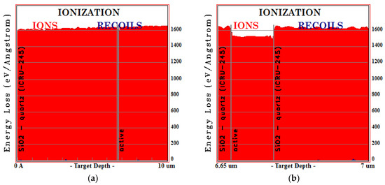
Aerospace Free Full Text Heavy Ion Induced Single Event Effects Characterization On An Rf Agile Transceiver For Flexible Multi Band Radio Systems In Newspace Avionics Html
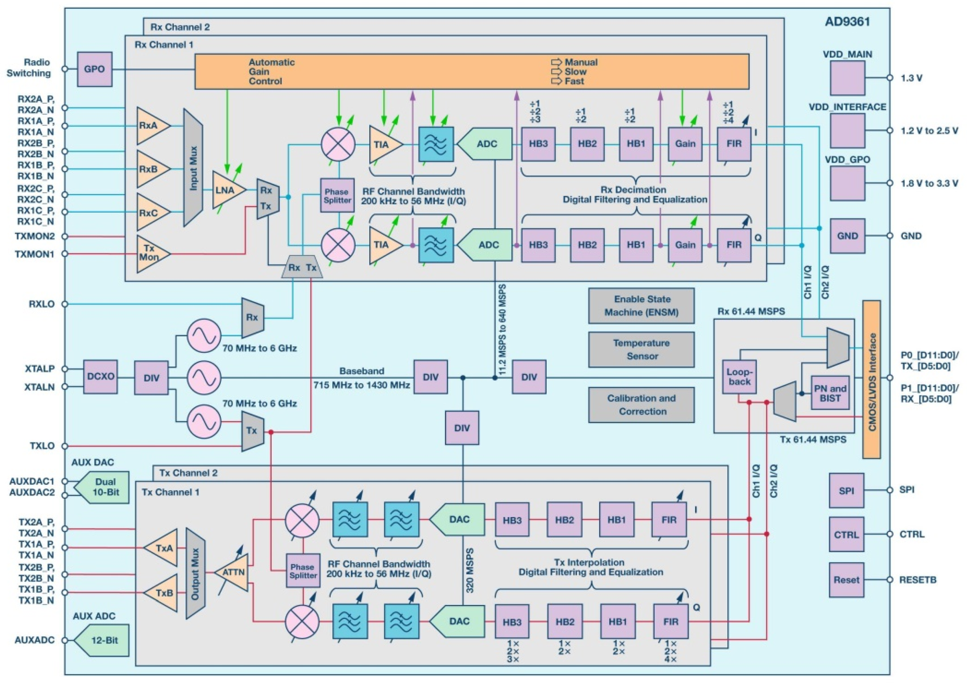
Aerospace Free Full Text Heavy Ion Induced Single Event Effects Characterization On An Rf Agile Transceiver For Flexible Multi Band Radio Systems In Newspace Avionics Html
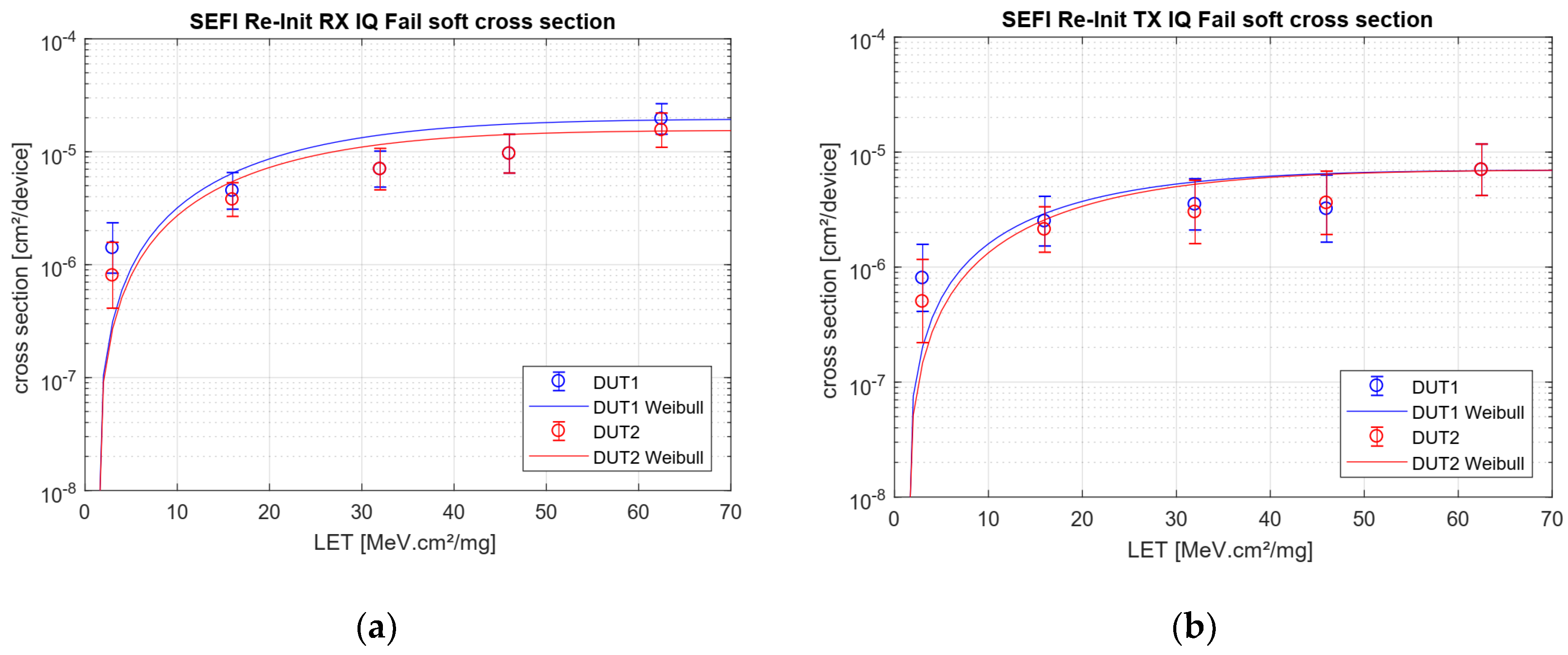
Aerospace Free Full Text Heavy Ion Induced Single Event Effects Characterization On An Rf Agile Transceiver For Flexible Multi Band Radio Systems In Newspace Avionics Html
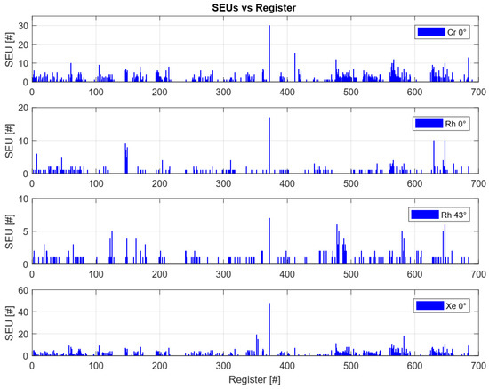
Aerospace Free Full Text Heavy Ion Induced Single Event Effects Characterization On An Rf Agile Transceiver For Flexible Multi Band Radio Systems In Newspace Avionics Html
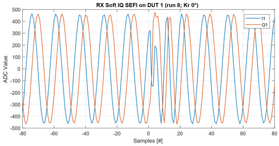
Aerospace Free Full Text Heavy Ion Induced Single Event Effects Characterization On An Rf Agile Transceiver For Flexible Multi Band Radio Systems In Newspace Avionics Html
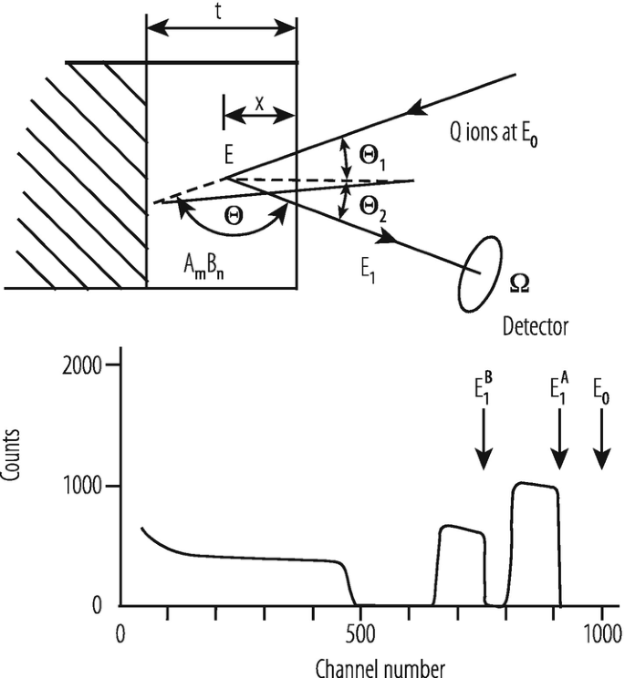
Application Of Accelerators And Storage Rings Springerlink

Lm567 A Detailed Introduction To Tone Decoder In 2022 Multi Core Processor Circuitry Circuit Diagram

Pdf Engineering Design Complexity An Investigation Of Methods And Measures
2
2
2
2
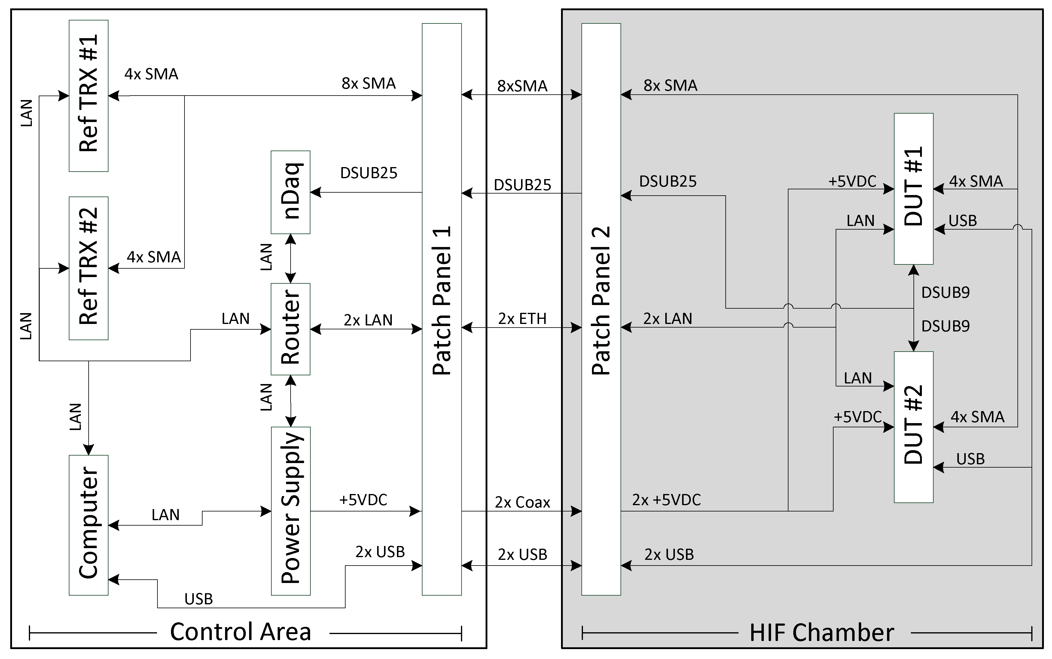
Aerospace Free Full Text Heavy Ion Induced Single Event Effects Characterization On An Rf Agile Transceiver For Flexible Multi Band Radio Systems In Newspace Avionics Html

Ne567 Datasheet Tone Decoder Phase Locked Loop And Example Circuits Simple Electronics Function Generator Circuit
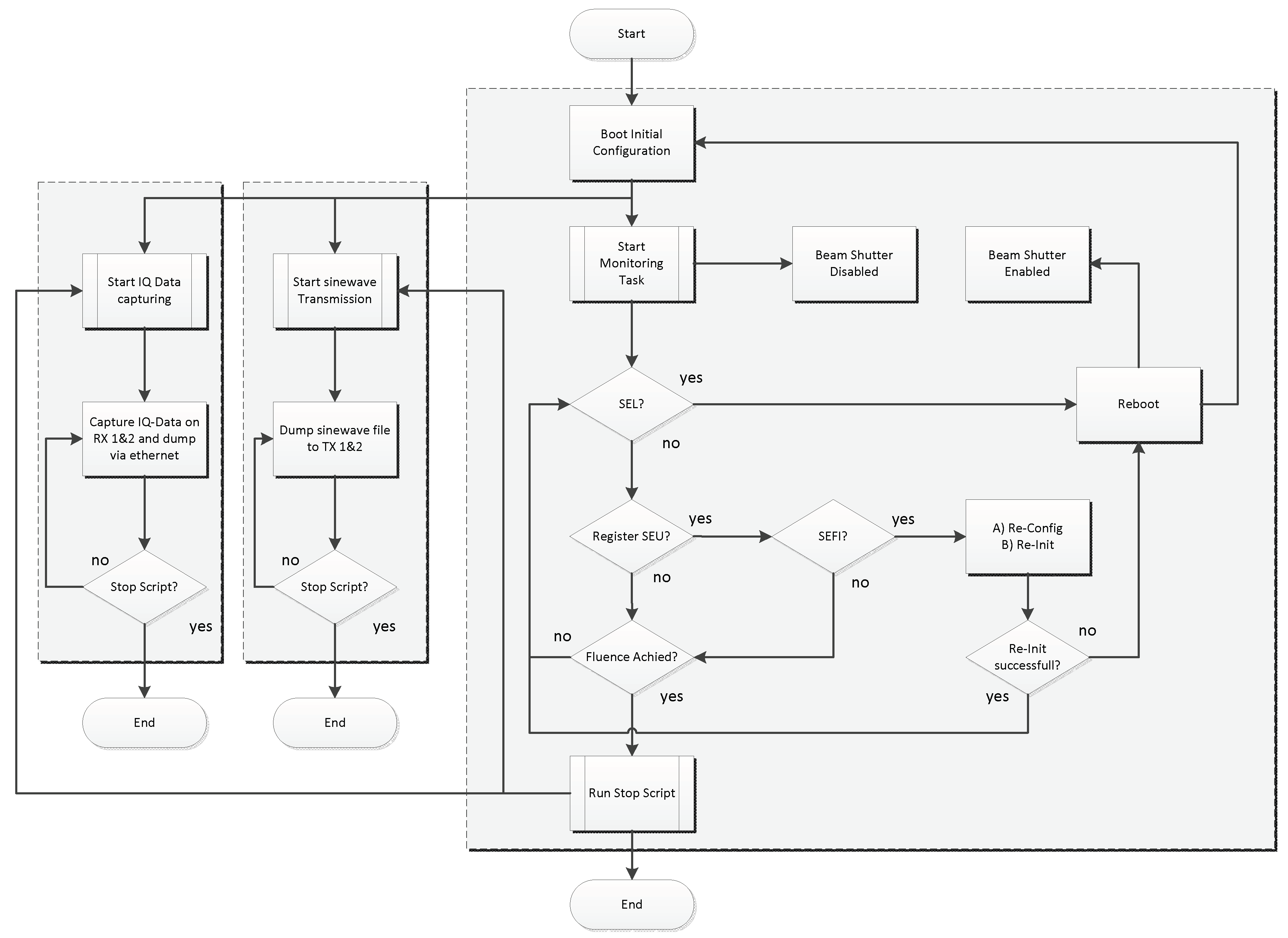
Aerospace Free Full Text Heavy Ion Induced Single Event Effects Characterization On An Rf Agile Transceiver For Flexible Multi Band Radio Systems In Newspace Avionics Html